初看之下,電力推進飛機的未來似乎希望渺茫。由于當下電池組的重量過大(即比能過低),電動飛機的發展受到了極大的限制。然而,得益于相關技術的近期發展,如今的電力推進(electric propulsion)系統憑借其特有屬性,將有潛力大幅提高飛機設計的靈活度,突破很多傳統燃料動力飛機的典型限制,從而帶來在過去看來并不實際,或根本不可能出現的新型飛機。這點在短途飛機的設計中尤為明顯,因為這類飛機的尺寸通常相對較小,多為活塞式機型。
由于尺寸和重量限制,以及活塞發動機的保養需求,多數活塞式機型在設計時僅能選用為數不多的幾種發動機(很多時候甚至只有1種可選),而且發動機的安裝位置也相對固定。如今,絕大多數的當代通用航空飛機和直升飛機看起來仍與上世紀50年代的機型非常相似,這就是其中的原因。通常來說,電驅動的動力總成系統的體積更小、質量更輕,而且結構非常簡單,有的系統甚至僅需要一個活動部件;而傳統的活塞發動機則復雜很多,至少需要冷卻系統、電氣系統、液壓系統,以及燃油系統等不同配置。
采用電動系統可以降低飛機的復雜度,從而減少維修保養的需求。一般來說,內燃機的體積越小,其功率質量比(power to weight)和能效就越低,而電機的性能則基本與大小沒有直接關系。這就意味著1-kW電機與1000-kW電機的功率質量比與能效幾乎沒有太大差別。
其次,電驅動的動力總成系統能效基本可以達到90%-95%,而傳統內燃機動力系統的能效在30%-40%之間,差距大約在3倍。此外,電機可以在更廣的轉速范圍內工作,而且轉速的改變也相對較快。最后,電動動力系統在運行時比內燃機系統安靜的多,任何接觸過電動車的人都能證明這一點。
雖然直接用電機替換現有飛機上的內燃發動機也可以帶來很多好處,比如降低噪聲、提高動力能效等,但從一開始設計飛機時就考慮采用電力推進系統則可以帶來更多優勢。由于這種系統的特殊屬性,工程師在設計時可以大量采用相對較小的電機,這并不會大幅增加系統的復雜度和保養成本,而且也不會犧牲電機的重量和性能。由于重量和體積都相對較小,這些電機在飛機上的安裝位置也非常靈活。此外,雖然電機僅會在飛行中的特定階段(比如起降階段)發揮作用,但由于其重量非常輕,因此額外配備這些電機幾乎不會帶來任何影響。
傳統的燃燒推進系統經常會犧牲飛機的性能,比如,牽引式螺旋槳造成的擦洗阻力(scrubbingdrag)就會增加機身上的反向速度。與此形成對比的是,靈活的電力推進系統不但不會犧牲飛機的性能,反而還能提升機身的空氣動力性能,其中一個做法是在翼尖位置安裝螺旋槳,回收翼尖渦流(wingtip vortices)損失的部分能量。
美國飛機制造商Joby Aviation已經設下目標,將利用電力推進技術開發數款新型飛機,預期可提供前所未有的超高性能。然而,由于飛機各個部分之間的互動非常復雜,而且缺少可以借鑒的現有設計,Joby公司在設計過程中,不得不進行大量高階空氣動力分析(aerodynamicanalysis)。在這場不同尋常的設計研發中,Joby公司通過工業軟件開發商CD-adapco公司的STAR-CCM+軟件,進行了大量CFD(計算流體動力學)分析。
Joby公司的主要研發對象是一款S2垂直起降(VTOL)飛機。由于噪聲大、運行成本高、飛行速度慢,而且安全系數也相對較低,直升飛機大小的傳統VTOL飛機的發展受到了嚴重的限制。在起降階段,S2飛機會同時啟用多個螺旋槳,通過冗余增加安全性。在巡航階段,S2飛機上絕大部分展開的螺旋槳會重新折疊收起,以減少飛行阻力。事實上,螺旋槳葉片的設計就是不斷在提升螺旋槳性能和降低飛行阻力之間做出平衡,這個過程需要高階工具進行合理的分析。Joby公司利用STAR-CCM+軟件,評估了多種不同運行環境下的螺旋槳設計,還對巡航階段的發動機艙進行了分析。結果顯示,改變螺旋槳葉片的形狀可以提高層流(laminar flow),并降低巡航阻力。
Joby公司另一個項目的研發對象是Lotus飛機,公司會通過一款重約55磅的無人機,探索創新VTOL飛機配置。在項目配置下,飛機的每個翼尖上均配備2個螺旋槳,可為飛機的垂直起飛提供推力。一旦飛機累積到一定程度的前向速度,足夠提升機翼,2個一組的葉片就會相互交叉起來,而每個獨立葉片也會成為翼尖的延續,形成一種剪刀型分列式翼尖。而機尾傾斜的尾槳則可以在起降過程中提供節距控制,并推動飛機向前方行駛。
可以想象,設計翼尖葉片要考慮跨度、翼型選擇、扭轉分布、弦分布及節距等各種參數,整個過程就是在螺旋槳和翼尖性能之間做出平衡。在巡航配置下,Joby公司通過交叉組合這些設計參數,進行了十多項CFD模擬,以期在滿足配置要求的前提下,取得最大化飛機巡航性能。同時,公司還通過CFD工具分析了螺旋槳配置中的葉片性能,以驗證低階設計方法的結論。
Joby公司的第三個項目是與美國國家航空航天局(NASA)和Empirical Systems Aerospace公司合作進行的LEAPTech(Leading Edge Asynchronous PropellerTechnology,前緣異步螺旋槳技術)研究。該項目的目標是研究電力推進系統可能給傳統固定翼飛機帶來的潛在提升。
研發人員會在機翼前緣安裝一組小型螺旋槳,從而在起降過程中增加機翼的速度,提升動壓(dynamicpressure)。這種設計可以增加機翼產生的提升,從而在相同的失速速度要求下,使用更小的機翼。很多小型飛機為了達到失速速度要求,而不得不采用較大的機翼,但較大的機翼會在巡航過程中影響飛機的性能,因此由于允許使用更小的機翼,這種設計能夠提高飛機的巡航階段的能源效率。
此外,由于機翼的負載更大,機上人員的駕乘體驗也能得到大幅提升。不過,低階工具很難分析這種吹氣機翼的性能,特別是多數所需的分析均發生在失速階段。因此,Joby公司在設計過程中進行了大量CFD模擬,分析研究了不同螺旋槳尺寸、功率、展弦比和沖角等參數的組合。為了縮減計算的成本,公司在使用STAR-CCM+工具時,將螺旋槳處理為具有螺旋槳體積力的驅動盤,從而減少葉片實際幾何形狀對分析的影響,大幅降低了所需的網格尺寸。
在該配置的測試中,Joby公司首先要建立一套全尺寸機翼、螺旋槳和電機,并將這些部件安裝在一個改裝的拖掛車上。接著,這輛拖掛車將在NASA阿姆斯特朗飛行研究中心(Armstrong Flight ResearchCenter)的跑道上,以飛機起飛的速度行駛。
與S2上的螺旋槳一樣,該配置下的前緣螺旋槳在起降階段之外,也會保持折疊收縮的狀態,而上文中提到的翼尖螺旋槳則會負責給飛機提供推力。雖然公司在評估這些螺旋槳可能對翼尖渦流造成的阻力和能效影響時,的確采用了低階分析法。但事實證明,CFD仍是迄今最可靠的分析法。按照計劃,一架演示機將在2017年起飛。
作者:Alex Stoll
來源:《SAE 航空工程雜志》
翻譯:SAE上海辦公室
Promise for an electric propulsion aircraft future
At first glance, it may seem that the excessive weight (i.e., low specific energy) of today’s batteries limits electric aircraft to, at best, a few trivial niches. However, the different properties of electric propulsion compared to traditional combustion power, coupled with recent technology advances, promise to significantly relax typical design constraints for many aircraft configurations, which will allow for new types of aircraft that were previously impractical or impossible. This is particularly true for shorter-range designs, which have traditionally been relatively small and piston-powered.
Because of the size, weight, and maintenance requirements of piston engines, most piston aircraft designs are limited to a small number of engines (often just one) located in a small number of practical locations. This is why most modern general aviation airplanes and helicopters look very similar to designs from the 1950s. In contrast, electric powertrains are much smaller and lighter, and they are incredibly simple—some having only a single moving part—compared to the relatively extreme complexity of piston engines, which include a coolant system, an electrical system, an oil system, a fuel system, and so forth.
This reduced complexity translates to much lower maintenance requirements. While smaller combustion engines suffer from lower power-to-weight and efficiency, electric motors are relatively scale-free. This means that the power-to-weight and efficiency will be similar between, for example, a 1-kW motor and a 1000-kW motor.
An electric powertrain is also about three times as efficient (around 90%-95% compared to around 30%-40%). Electric motors can operate well on a much wider range of rpms, and they can change rpm relatively quickly. Finally, electric powertrains are significantly quieter than combustion powertrains, as anyone who has heard an electric car can attest.
While simply replacing a combustion engine with an electric motor will see the benefits of lower noise and higher powertrain efficiency, much greater advantages can be gained by designing an aircraft with electric propulsion in mind from the start. The different properties of electric propulsion mean that aircraft can effectively employ a large number of small motors without incurring an undesirable amount of complexity (and maintenance costs) and without sacrificing on motor weight or performance. These motors can be located in a much larger range of positions on the aircraft, due to their relatively low weight and small size. Additionally, the compromises of carrying motors that are only used in some portions of the flight (e.g., takeoff and landing) are relatively minor, since the motors themselves are so light.
While traditional propulsion installations often compromise aircraft performance—for example, the scrubbing drag caused by a tractor propeller increasing the velocity over the fuselage—the flexibility of electric propulsion allows for propulsion installations that actually result in beneficial aerodynamic interactions. One such example is locating propellers on the wingtips, where they can recapture some of the energy lost to the wingtip vortices.
Joby Aviation has set a goal to capitalize on the promise of this new technology to develop several aircraft providing capabilities that were never before possible. However, due to the complex nature of these interactions and the lack of previous designs to extrapolate from, a large amount of high-order aerodynamic analysis had to be performed in the design process, and Joby leaned heavily on CFD analyses using CD-adapco's STAR-CCM+ in the development of its unconventional designs.
Joby’s main development effort is the S2 vertical takeoff and landing (VTOL) aircraft, which addresses the high noise, high operating costs, low speed, and relatively low safety levels that, together, have severely limited the proliferation of conventional VTOL aircraft of this size (helicopters). The S2 employs multiple propellers in takeoff and landing to increase safety through redundancy. In cruise, most of these propellers fold flat against their nacelles to reduce drag. The design of these propeller blades is a compromise between propeller performance and the drag of the nacelles with the blades folded, and higher-order tools were required to properly analyze this tradeoff. A variety of propeller designs were assessed under various operating conditions in STAR-CCM+, and the nacelle was analyzed in the cruise configuration. Results indicated where reshaping the propeller blades may increase laminar flow and reduce cruise drag.
Another Joby project is the Lotus aircraft, which is exploring an innovative VTOL configuration on the 55-lb UAV scale. In this aircraft, two-bladed propellers on each wingtip provide thrust for vertical takeoff. After the aircraft picks up enough forward speed for sufficient wing lift, each set of two blades scissors together and the individual blades become wingtip extensions, forming a split wingtip. A tilting tail rotor provides pitch control during takeoff and landing and propels the aircraft in forward flight.
As one may expect, the design of these wingtip blades—the span, airfoil choice, twist and chord distribution, pitch, and dihedral—was an interesting compromise between propeller and wingtip performance. Dozens of CFD simulations were run on different combinations of these design variables in the cruise configuration, to maximize the cruise performance within the constraints of the configuration. At the same time, the performance of these blades in the propeller configuration was also analyzed with CFD to validate lower-order design methods.
A third project Joby is participating in is LEAPTech (Leading Edge Asynchronous Propeller Technology), a partnership with NASA and Empirical Systems Aerospace. The goal of this design is to investigate potential improvements in conventional fixed-wing aircraft through electric propulsion.
A row of small propellers is located along the leading edge of the wings and, during takeoff and landing, these propellers increase the velocity (and, therefore, the dynamic pressure) over the wings. This increases the lift produced by the wing and allows for a smaller wing to be used for the same stall speed constraint. Since many small aircraft use a wing sized to meet a stall speed constraint but too large for optimal cruise performance, this smaller wing allows for more efficient cruise.
Additionally, the ride quality is significantly improved due to the higher wing loading. However, the performance of this blown wing is difficult to analyze with lower-order tools, particularly since much of the required analysis occurs around stalling conditions. Therefore, a large number of CFD simulations were performed in the design process, looking at various combinations of propeller sizes and powers, wing aspect ratios and sizes, angles of attack, etc. To reduce the computational expense, the propellers were modeled as actuator disks with the body force propeller method in STAR-CCM+, which negated the need to resolve the actual blade geometry, drastically decreasing the required mesh size.
The first phase of testing this configuration was to build the full-scale wing, propellers, and motors, and mount them above a modified semi-truck which was run at takeoff speeds on the runway at NASA Armstrong Flight Research Center.
Outside of takeoff and landing, these leading-edge propellers are planned to fold against their nacelles—similar to the S2 propellers—and wingtip propellers, as mentioned above, will provide propulsion. Although lower-order analysis methods were evaluated for estimating the drag and efficiency impact of operating these propellers concentric with the wingtip vortex, unsteady CFD proved to be the most reliable analysis method. A flight demonstrator is planned for flights beginning in 2017.
This article was written for Aerospace Engineering by Alex Stoll, Aeronautical Engineer, Joby Aviation.
Author: Alex Stoll
Source: SAE Aerospace Engineering Magazine
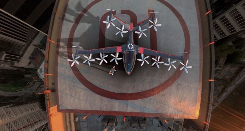 Joby Aviation公司的S2飛機。
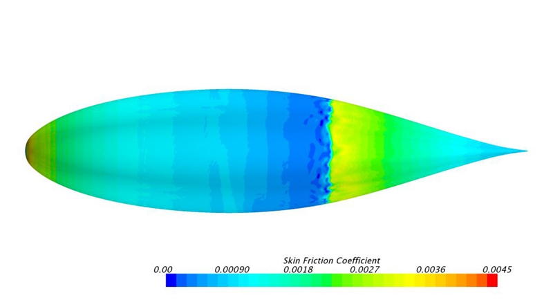 針對S2發動機艙的CFD分析,展示了干凈利落的發動機艙(如圖所示)與帶有折疊葉片和轉盤間隙的發動機艙(下圖)之間的對比。
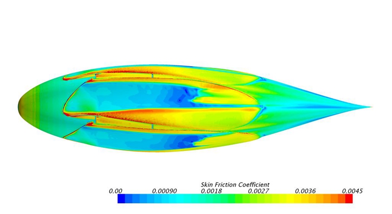 針對S2發動機艙的CFD分析,展示了設計干凈利落的發動機艙(前圖)與帶有折疊葉片和轉盤間隙的發動機艙(如圖所示)之間的對比。
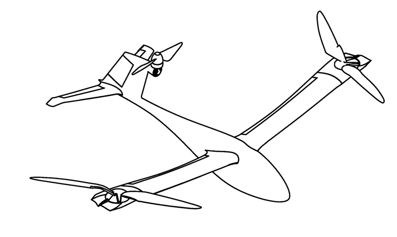 起飛配置下的Lutos形態。
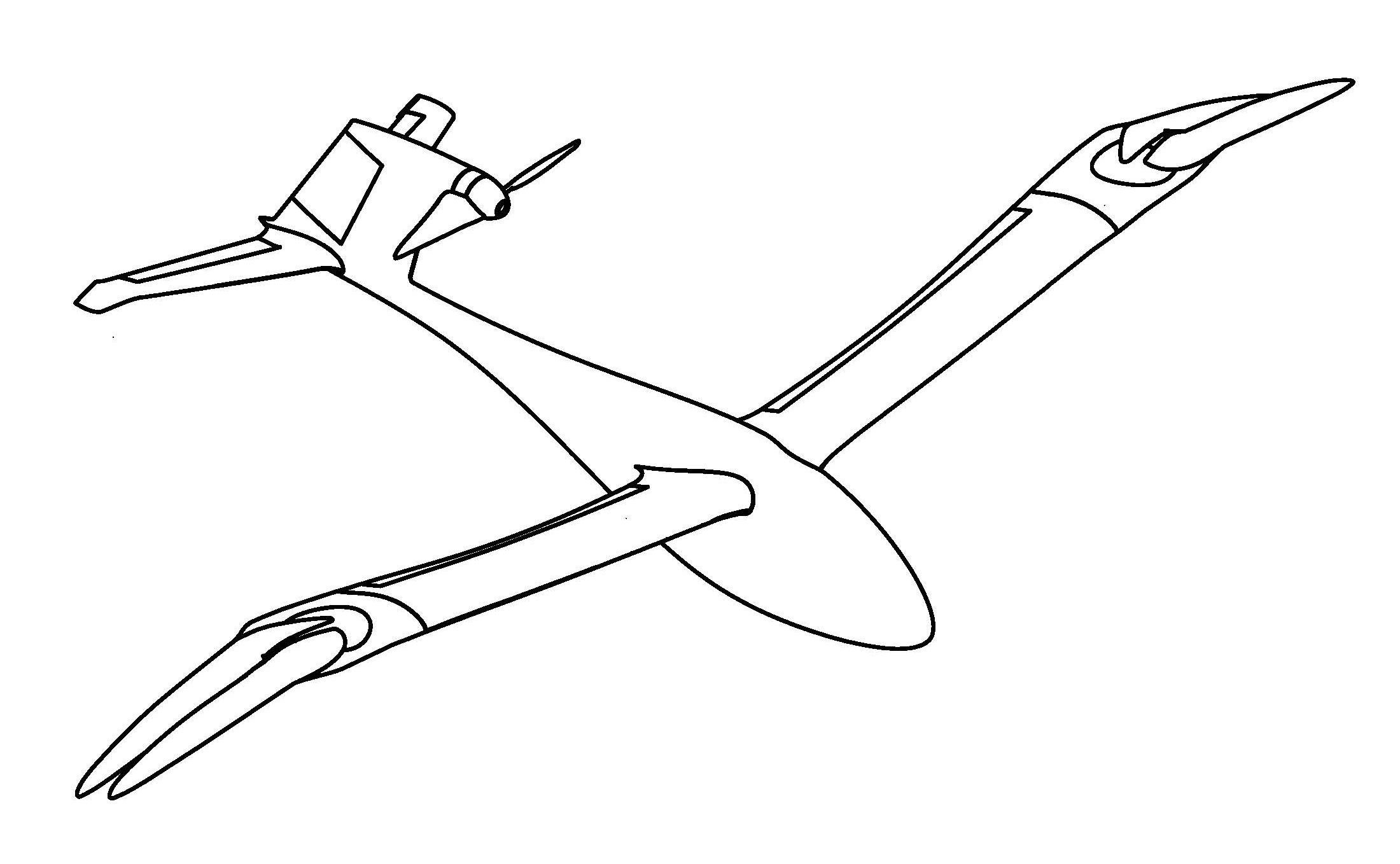 巡航配置下的Lutos形態。
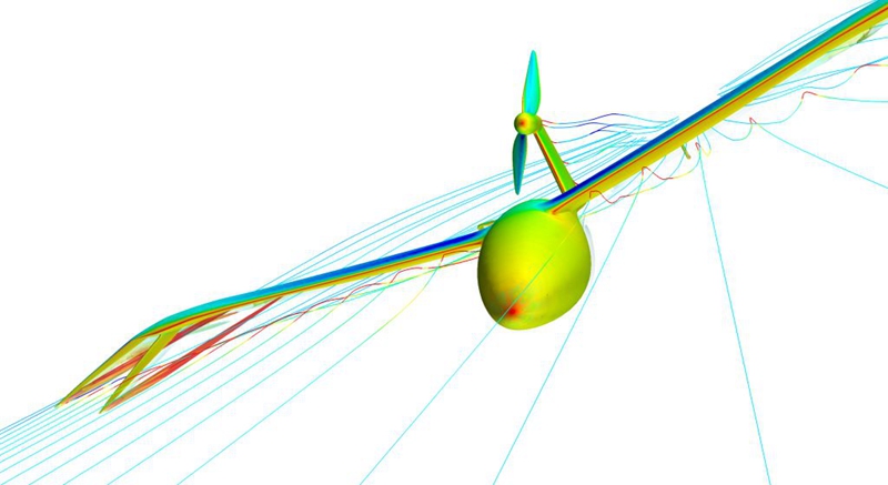 針對巡航配置下的Lutos進行CFD分析。
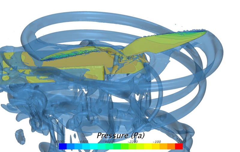 針對起飛配置下的Lutos翼尖螺旋槳進行CFD分析。
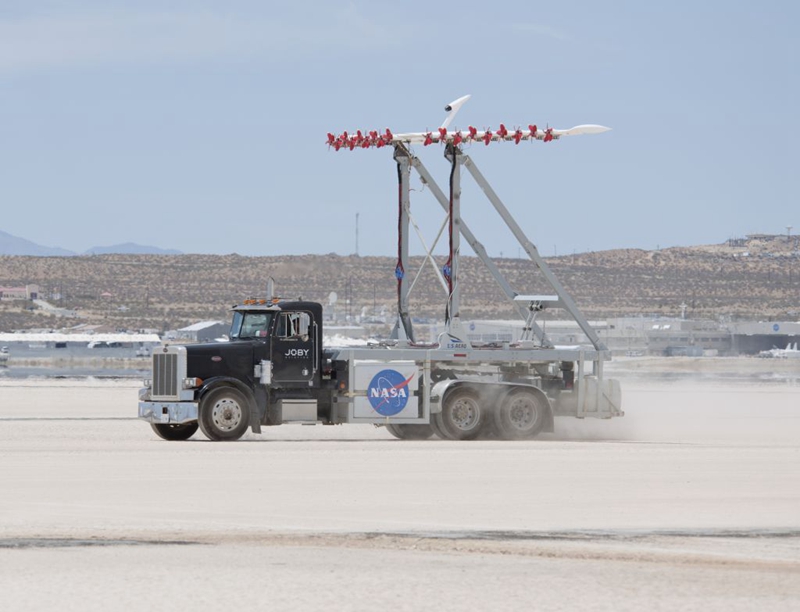 NASA阿姆斯特朗中心的LEAPTech實驗測試設備。(NASA)
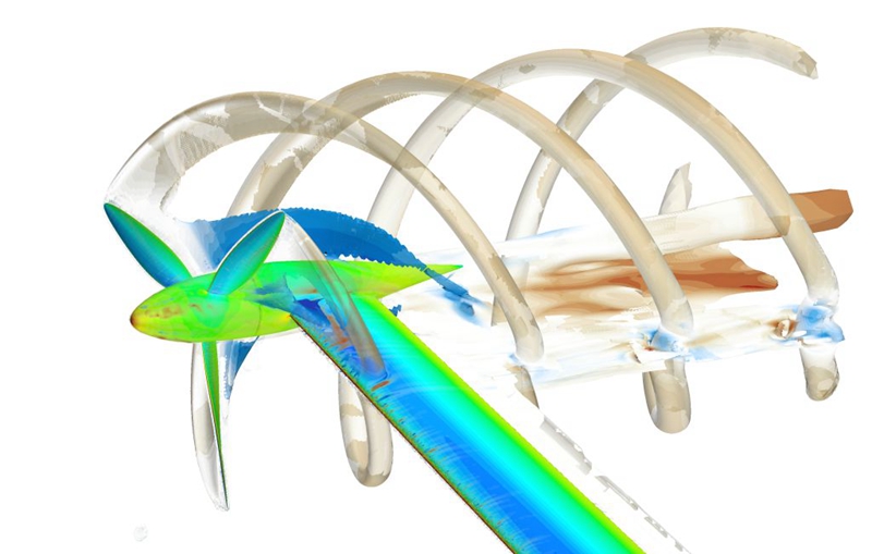 針對翼尖螺旋槳的CFD模擬。
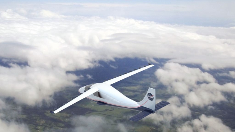 LEAPTech項目的演示機。(NASA)